
The ANSI/VITA 65 (OpenVPX) standard began early in 2009 in the OpenVPX Industry Working Group, and forms a system-level framework for VITA 46/VPX interoperability. OpenVPX is very flexible, providing high performance for a variety of different applications. Different types of applications tend to utilize different system architectures, requiring different backplane connectivity.
A key area of discussion is how to integrate a system with interoperable modules. OpenVPX Profiles provide structure for this process. Weighing in at more than 400 pages, the new OpenVPX standard can be a bit daunting though. ANSI/VITA 65’s total of fifteen 6U backplane profiles, fourteen 6U module profiles, thirteen 3U backplane profiles, and twenty-two 3U module profiles seems like a lot of alternatives from which system integrators can make choices. The good news is that it’s not as complex a task as it first appears to be.
The following discussion will provide hands-on guidance for navigating the new standard, selecting appropriate backplane profiles, and matching up compatible modules and backplanes, all in an effort to ensure proper chassis selection. Specifically, we will look at:
- Criteria for development chassis selection and OpenVPX-compliant cooling
- OpenVPX compatibility between power profiles and backplane and development chassis
- Serial fabric protocols and OpenVPX chassis deployment
An overview: Development chassis selection
OpenVPX provides a number of recommended profiles for development chassis selection. This covers the basics such as slot count, module type, module size, cooling, and power. OpenVPX targets power and cooling to handle 75 W per slot in 3U, and 150 W per slot in 6U.
Key decisions include:
- Cooling methods
- 5 V-centric power allocation profile versus 12 V-centric power allocation profile
- Backplane profile
- Fabric protocols and baud rates
- Chassis style
Let’s look at these decisions vital to development chassis selection – and how to best solve their associated challenges.
OpenVPX-compliant cooling
An important chassis selection criterion is cooling. The power dissipation of VPX-based modules is often much higher than traditional VME- or CompactPCI-based modules, which usually top out at around 100 W; most VME or CompactPCI modules are <40 W. Until now, there was no standardization of the power or the cooling of a development chassis. ANSI/VITA 65 has changed that, providing for the first time specific criteria for development chassis power and cooling; this is generally 2x to 4x the power and cooling that typical COTS VME or CompactPCI development chassis can provide.
The ANSI/VITA 65 OpenVPX standard requires 18 CFM per slot at 0.24 in H2O at 5 kft for air-cooled development chassis. This is an extremely high level of cooling, so very few existing chassis are capable of delivering this cooling. This is intended to handle the vast majority of modules that exist today, so it may be overkill for some low-power VPX applications; for example, Intel Atom-based SBC modules typically dissipate <15 W, whereas DSP-oriented multiprocessor and FPGA modules are often in the 100 W to 150 W range.
Power profiles to suit the application
Another important chassis selection criterion is the power profile, as mentioned earlier. OpenVPX recommends 5 V-centric and 12 V-centric power profiles that should handle most applications. Selecting one or the other depends on the power usage of the specific payload modules that will be installed. Applications with a mix of payload with 5 V-centric and 12 V-centric power profiles may require a modified development chassis power supply configuration, but this is a simple modification. The appropriate power profile depends on the sum of the selected payload modules’ power requirements.
The backplane: A pivotal consideration
Selecting an appropriate backplane profile is a key decision factor; the backplane topology needs to support the application requirements as well as providing compatibility with the selected payload module profiles. Backplane profiles are intended for specific types of applications, for example:
- Master-slave Control Applications – Profiles minimize size and cost.
- High-performance Multiprocessing Applications – Profiles maximize Data Throughput.
- Daisy Chain and Mesh Topologies – Profiles maximize efficiency for small slot counts (typically 5 slots or less).
- Central Switch Topologies – Profiles provide higher performance for large slot counts (typically >5 slots).
Figure 1 depicts the differences between a backplane profile intended for multiprocessing applications versus a backplane profile intended for control applications. The difference in complexity is evident, as is the 2-slot overhead for the complex switch slots in the multiprocessing profile. The profile on the left supports multiple planes (data, control, and expansion), with equal latency performance through the central switches; this provides a lot of connectivity bandwidth for multiprocessing. The profile on the right is typical for control applications with an SBC controlling several peripherals through a single data plane (typically PCIe); this provides a simpler, lower-cost alternative for control applications.
Matching up fabric protocols and baud rates
Serial fabrics such as Serial RapidIO, PCI Express, and Ethernet all have several different possible data rates. It is necessary to match the module fabric protocols for each serial plane in the backplane, and to match the module and backplane baud rates for each serial plane in the backplane.
More than one module profile may be compatible with a particular slot on a particular backplane profile. VITA 65 lists a single slot profile <=> single module profile, but there may be some other module profiles that are compatible. Compatibility depends on the connector pins and signals connected in the specific backplane profile. Additional module profiles may be compatible. All of the signals connected on the backplane must match up with defined signals of the same type on the modules; they may have additional defined signals not connected on the backplane, but that’s OK to ensure compatibility of the module and the slot. For example, the module profile may have control plane and/or expansion plane signals defined that are not connected in the backplane profile; the module can be used in this slot as long as the application doesn’t need to have these additional signals connected in the backplane. Fabric protocols and baud rates for modules at both ends of backplane profile connections must match up as well. To make this easier, all the compatible module profiles for available standard OpenVPX backplanes have been identified.
For example, OpenVPX backplane profile BKP6-DIS05-11.2.16-n lists OpenVPX peripheral module profile MOD6-PER-4F-12.3.1 as the compatible module profile. OpenVPX payload module profile MOD6-PAY-4F1Q2U2T-12.2.1-x is also compatible with OpenVPX backplane profile BKP6-DIS05-11.2.16-n. OpenVPX payload module profile MOD6-PAY-4F1Q2U2T-12.2.1-x also has defined Control Plane and Expansion Plane pinout, but these are not used in the OpenVPX backplane profile BKP6-DIS05-11.2.16-n, so they would be available for rear I/O.
Moving OpenVPX out to deployment in chassis-compatible style
The OpenVPX standard does not explicitly address deployed system configurations, but the module profiles and backplane profiles can be readily leveraged for deployed applications in regard to chassis compatibility. Standard or modified OpenVPX profiles can now be used in many deployed applications.
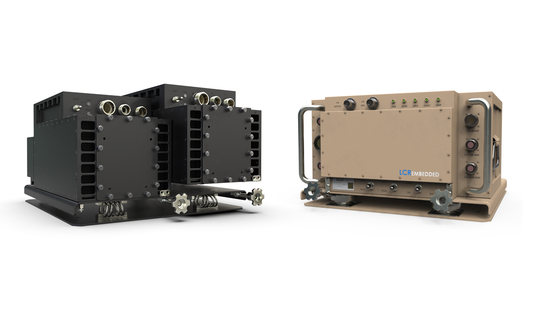
Vendors such as Curtiss-Wright provide OpenVPX-compliant development chassis and backplanes supporting most OpenVPX module profiles. Accordingly, Figure 2 shows an example of OpenVPX moving into deployment applications: a forced-air, conduction ATR solution for an airborne signal-processing application based on COTS VME and OpenVPX modules. Although the backplane is custom, it is based on standard OpenVPX slot profiles. This 1,400 W chassis has a 16-slot hybrid 6U VME64x/OpenVPX backplane and high-performance military fans for operation at 50,000 feet. At 1,400 W, the power level is very high compared to traditional VME or CompactPCI applications, and this will be the case for many OpenVPX applications.
OpenVPX provides answers
The ANSI/VITA 65 OpenVPX standard provides a framework for VPX system-level interoperability. This was the key goal of the OpenVPX effort, and it is working. Interoperability starts in the development lab, where choosing an appropriate OpenVPX development chassis is imperative. The good news is that OpenVPX defines standard development chassis profiles, module profiles, and backplane profiles that can be used to perform initial development.
The standard OpenVPX profiles can also be used as a starting point to address deployed system configurations and deployed chassis, and the standard module profiles and backplane profiles can be readily leveraged for deployed applications. This is already happening.
Curtiss-Wright Controls Electronic Systems 978-772-5422 www.cwcelectronicsystems.com