At the recent Components for Military and Space Electronics Conference and Exhibition in San Diego1, editor Sharon Schnakenburg and I were introduced to a radical new technology called Imbedded Component/Die Technology that can conceivably provide more than 2x the energy density on a typical 6U VME LRU. I’m extremely encouraged about the possibilities, and several DoD programs, along with the Navy’s Standard Missile program office, agree with me. (And yes, the company intentionally spells "Imbedded" with an "i" for differentiation.)
You see, with AMD, Freescale, IBM, and Intel multicore CPUs pushing 40 W or more2, the prospect of liquid-cooled VME boards is actively being discussed in VSO by our industry’s leading COTS suppliers and military contractors. 80-ish total watts is typically considered the "practical limit" for even the most exotic IEEE 1101.2 conduction-cooled board, but that won’t be nearly enough when vendors pack on several quad cores, PCI Express, multiple GbE ports, a graphics processor doing FFTs, Serial RapidIO, plus PMC, XMC, or VITA 57 FPGA mezzanine cards. Where’s all that heat going to go? More to the point: Is there enough front- and back-side real estate just to fit all these components?
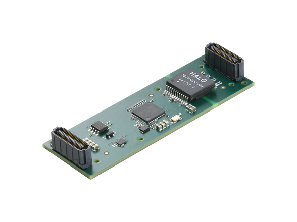
STI Electronics (which started out in the 1960s as Soldering Technology Interna-tional working with NASA and NAVAIR China Lake) has patented (No. 7,116,557) the ability to mount packaged components and bare die in tiered encapsulated cavities in standard multilayer, core-cooled FR4 PWBs. The theory is simple; the actual practice is pretty simple, too. With high-power and high-pinout devices, a lot of the IC’s footprint and height is consumed by the package lead frame and internal heat sink. Removing all that junk and mounting the die directly to the PWB consumes less than 20 percent or more of the packaged footprint.
Moreover, die directly mounted to a center core of aluminum or copper can directly conduct heat away by removing multiple thermal resistance paths presented by the package, heat sink, PWB, or other material. Actual STI tests on high-power transistors reduced the die temperature from 162 °C to 35 °C at the same ambient. Empirical thermal models predict similar temperature reductions in most active digital devices. Additionally, by eliminating pin and lead/ball frame parasitic resistance and inductance, faster signal propagation is possible between the transistors and the off-die world. Once in the PWB itself, common high-frequency routing is used. However, since many die components can now be mounted closely together in common cavities (such as Ethernet MAU, transceivers, pull-ups, and bus interface), on-card routing is actually simplified.
For high rel systems, the IC/DT approach has other benefits besides energy and real estate density. Die weigh less than packaged parts, so overall board mass is reduced – handy for UAVs, avionics, or manpacks. And with components closer to the PWB and not cantilevered sometimes tens of millimeters above the PWB surface, vibration tolerance is increased and resonance frequencies are more manageable. This was a key factor in the Navy’s recent successful test using an IC/DT board in an SM-2 Block IIIA Standard Missile launched off the Aegis class USS Kidd in October 2007.
But will this technology work for 6U conduction-cooled VME or 3U VPX boards? There’s no reason it shouldn’t, says Mark McMeen, V.P. of Engineering at STI. The company has received several Phase II SBIR awards, one of them requiring the integration of 8 high pin count digital ICs and their associated memories per board side – totaling 16 high-power devices per LRU. Though STI wouldn’t tell me the application or device types, the digital ICs are "on the order of 1,000 pins each." No way all that would fit on a 6U board; probably not even on two boards – much less cooling all these components.
Who would want this kind of density? High rel applications where SWaP is paramount, we were told. Clearly that’s not every military program, so standard IEEE 1101.2 has nothing to fear. But at a projected price of only 1.2x to 1.4x over the typical conduction-cooled board – the IC/DT concept definitely warrants further investigation.
I know I’ll be staying in close touch with STI. This literally is cool stuff.
Chris A. Ciufo
[email protected]
1. See http://www.cti-us.com/cmsecover.htm. Full disclosure: VME and Critical Systems as well as our magazine Military Embedded Systems were both sponsors of this event.
2. As we went to press, AMD announced its new 65 watt Phenom X4 9100e quad-core processor.

