Architectures such as VXS and VPX use more power and run hotter than legacy buses like VME and CompactPCI. VXS cards often run at 80 W to 100 W per slot, while VPX cards are typically 100 W to 150 W per slot. In a 10-slot ATR enclosure, that is up to 1,500 W (10 x 150 W) to dissipate. The challenge is to cool the chassis, given virtually zero airflow in many ATR applications, and a finite (and fixed) amount of space.
There are various cooling methods for ATRs. Some possibilities include air, conduction, and liquid cooling or hybrids of these styles. Forced air cooling is a common method; however, in ATR applications, the environment is sometimes sealed or otherwise has little air for entry and exit. There are also issues with Electromagnetic Compatibility (EMC) and filtering in such applications, but we’ll focus primarily on conduction and liquid cooling.
Conduction cooling: A good solution, with limits
Stand-alone conduction cooling is an excellent solution for many designs, particularly for high-altitude or other applications where airflow is limited. However, it alone cannot be used in all designs, as you reach the limits of heat dissipation and removal. The heat generated within the enclosure is conducted from the heat sources on the boards through to the outer surfaces of the enclosure, and the heat is then given up to the ambient air. Internal heat pipes can be used to improve the system’s efficiency without introducing electromechanical moving parts. However, while it’s the simplest and therefore most reliable method, conduction cooling is also the least efficient. A conduction-cooled ATR will typically be rated in excess of 50 W per slot. So, some applications may necessitate a little assistance to transfer more heat.
Liquid cooling: Finding a practical and cost-effective form
Liquid-Flow-Through (LFT) and direct spray methods are perhaps the most aggressive ways to cool a chassis. However, these methods are among the most complicated and expensive choices available. Spray cooling, whether mist or liquid, brings issues such as:
- Water buildup
- Single point-of-failure
- Costs
- Complexity
- Space required
- Mean Time to Repair (MTTR)/Mean Time Between Failure (MTBF)
LFT, where the liquid runs directly through each module, can also be costly and complex. However, this method may be an effective choice for the most demanding thermal management applications. Theoretically, VPX cards can use 48 V at 16 A, which is 768 W per slot. Typical VPX conduction-cooled modules today are 5 V and 12 V, with wattages in the 100 to 150 W range. When VPX modules push on the higher wattage levels in certain designs, LFT may be the right way to go. But, there is another solution to cool this wattage range with a much simpler and more cost-effective solution: Liquid Heat Exchange (LHE).
LHE: A practical choice
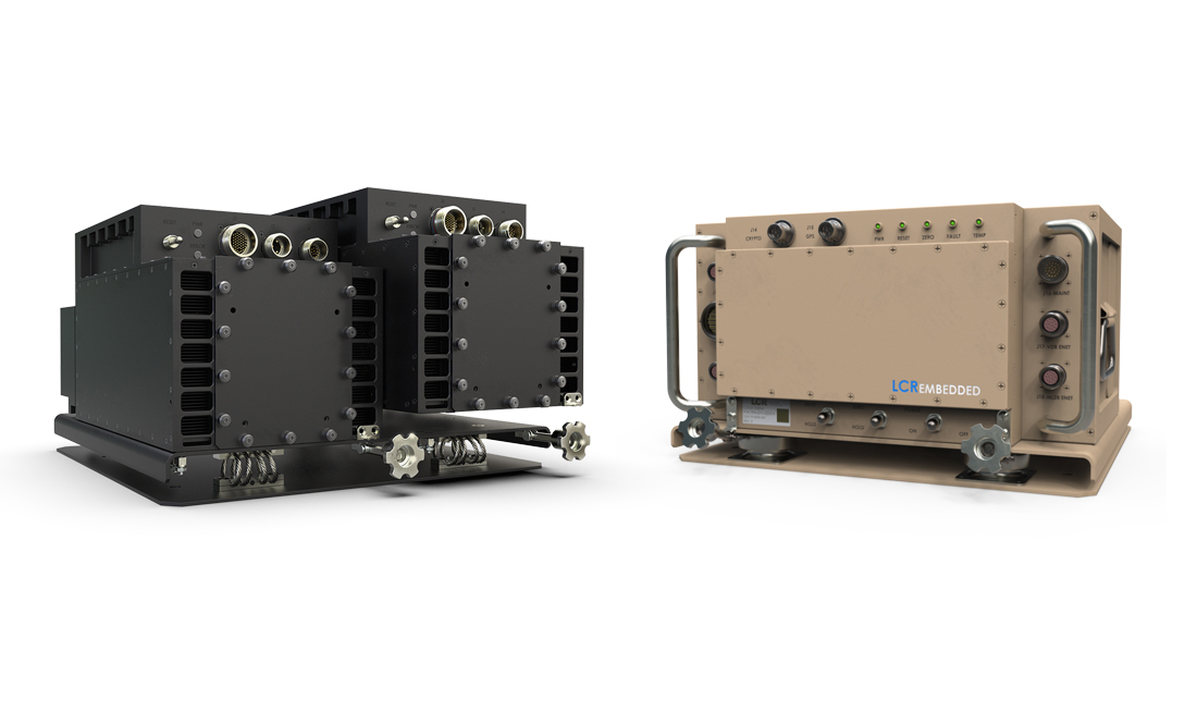
LHE uses the sidewalls of the chassis for plumbing the liquid. An ATR, such as the one shown in Figure 1, uses a modular liquid-heat-exchange method to transfer excess heat from VXS or VPX conduction-cooled cards. This provides much more heat transfer than conduction alone. As the liquid is in a fixed area (the walls), engineers do not get into a messy situation with plugging/unplugging liquid modules. The modules for this design style are the same VXS or VPX conduction-cooled ones described earlier. The side plate assembly consists of precision-machined sidewalls, fluid carrying pipes configured to avoid sharp bends, thermally conductive inserts, and clamping brackets that can quickly be replaced as a complete subassembly in the field. The LHE design supports a thermal budget of 1,500 W in a 10-slot 1 ATR size, enabling a wide range of the latest high-performance boards to run well within their operating temperature envelope. Thermal imaging, like the example shown in Figure 2, can be used to find the hotter parts of the chassis. From there, the designer can incorporate solutions to optimize the cooling.
A dual wall modular design subassembly can also significantly reduce MTTR. The cooling sidewalls can operate as Line Replacement Units (LRUs), so a swap out is a simple process that can be carried out in the field. Each side plate has its own independent feed and return. Cooling is still provided in the event of damage to one side; the design also avoids running pipe work across the rear face of the chassis, the area most likely to be damaged if the unit is accidentally dropped. Various materials, protective coatings, and connectors can be used, enabling aviation fuel, Chlorofluorocarbons (CFCs), ammonia, or various alcohols to be implemented as the cooling fluid to suit the application. Seawater, typically at a temperature of +15° C, can also be used, which has obvious cost and availability benefits for naval applications.
It might appear strange to use kerosene as a cooling medium; however, there are significant advantages for avionics applications. The fuel is already pumped around under pressure, so a dedicated pump is not required, saving weight and space. The fuel sits at -30 °C in the fuel tanks, and therefore, it must be preheated before it can be burnt in the engine. The heat produced in the ATR, together with the waste heat from avionics and other systems, is transferred into the onboard fuel before it is fed to the main propulsion unit, reducing preheat requirements.
A solution found
We can tackle the thermal management challenges that new technologies such as VXS and VPX bring to avionics. Conduction cooling can solve the problem in many ATR applications, but only get us part of the way there in the higher-wattage applications. Adding LHE to dissipate heat in conjunction with conduction-cooled modules can solve the problem for many of today’s applications at significantly reduced cost and complexity.
Elma Electronic Inc.
510-656-3400
www.elma.com

