Perhaps one of the most challenging aspects of board design is in the area of I/O design and management; systems require digital I/O for USB, Ethernet, SATA, optical, and much more, plus the incredible number of analog to digital (ADC) and digital to analog (DAC) interfaces needed. Embedded computing systems rarely have a common subset of I/O needs because of the wide range of applications and markets covered; therefore, flexibility is demanded when it comes to I/O functionality on boards. Typically, this I/O functionality is in a fixed location on the computer board, or it was configured with mezzanine boards like PMC or XMC modules. These modules provide configurable I/O, but they use much of the carrier card area and incur, in some cases, unacceptable data overhead and system complexity because of the PCI or PCI Express bus interface between the host and the mezzanine.
A change in market requirements can typically lead to a change in I/O functionality, causing a difficult and expensive board respin to relocate connectors, change connector types, or add or delete functionality. Over the past two decades, designers have depended more heavily on FPGA technology to implement this I/O. FPGAs enable designers to create custom I/O or utilize libraries of off-the-shelf IP for USB, Ethernet, SATA, optical, and much more. Furthermore, FPGAs are used to “package up” the data for transfer over the mezzanine card connector, for example PCI. This helps with the cost of the host platforms, but it requires a substantial list of modules to be developed to achieve a highly robust product line and a wide range of technical knowledge to understand not only the external I/O but the mezzanine-to-host protocols as well.
Standing on the shoulders of giants
The leading FPGA suppliers, Xilinx and Altera, advocate the use of modular I/O as a front-end to their FPGAs and development kits.
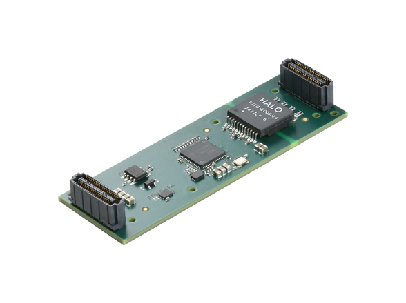
Xilinx adopted the FPGA Mezzanine Card (FMC) standard, created within the VITA 57 working group, as their architectural foundation for a modular I/O capability for their development kits. FMC is a standard method focused on putting I/O devices on mezzanines connected to and directly controlled by FPGAs residing on a host or carrier card.
“FMC has rapidly become the de facto standard for daughtercards in the FPGA industry,” stated Raj Seelam, Sr. Marketing Manager, Platform Solutions at Xilinx. “We now have a thriving ecosystem in place for FMC that offers users a wide variety of I/O options to customize their designs. Our customers can use the same FMC with multiple generations of Xilinx FPGAs, which protects their R&D investments and accelerates their design cycles at the same time.”
Altera developed the High-Speed Mezzanine Card (HSMC) specification to standardize the interface of mezzanine cards to host boards. Altera and partners offer a variety of host platforms and mezzanine cards that comply with this specification. Altera is now creating development kits with FMC capabilities reinforcing the benefits of standardization.
The purpose of the FMC is to allow an FPGA on a host card to connect directly with the I/O devices on the mezzanine module – just as if the devices were on the host board. This intimacy means the interface can be optimal and removes the protocol “fat” and legacy shackles. Savings are made in design time, real estate, cost, and power, while maintaining maximum bandwidth with minimum latency. The FMC standard is described in ANSI/VITA 57.1 and defines a small form factor I/O mezzanine card that can be connected to most carrier board form factors. It assumes that FMCs connect to an FPGA device or other device with reconfigurable I/O capability.
The FMC standard is FPGA architecture independent and is designed to:
• Maximize data throughput (potential for more than 40 GBps
• Minimize latency (copper track delays only)
• Reduce FPGA design complexity (no additional protocol overheads)
• Minimize system cost (smaller FPGA real estate, fast design times)
• Reduce system overhead (reduced power and cooling needs)
The standard describes FMC I/O modules and introduces an electromechanical standard that creates an extremely low overhead bridge between front panel I/O on the mezzanine module and an FPGA processing device on the carrier card, which accepts the mezzanine module.
FMC takes a new approach on interface protocols by removing the need to inject protocol data into the raw data to be processed as what happens with a defined bus interface. It assumes that the FPGA has a unique closeness with the I/O mezzanine module. This enables the FMC standard to capitalize on the unique reconfigurable capability of FPGAs to process natively the raw data formats that the module sources and sinks. Rather than get into defining functionality for the pins, FMC simply defines the upper limit of connections for both parallel lines and multigigabit serial signals.
“The ability to place signals anywhere on [the] FMC is generally helpful,” according to Jim Mooney, Director of Sales and Marketing at Integre Technologies, LLC. “Having more signals available on the FMC than are used in the design allows for optimized spacing and routing of sensitive signals. You do have to be careful if the design demands that signal groups target the same I/O banks of the FPGA, as this can be different for each FMC carrier.” Since each design is different, a comparison of different mezzanine capabilities is shown in Table 1, courtesy of Curtiss-Wright Controls Defense Systems.
Rapid solutions
Businesses and engineers are measured on delivering results, rapidly. FMC provides a path to de-risking developments and opens up the availability of knowledge within the precipitously expanding FMC ecosystem.
“The FMC standard reduces design costs and time-to-market by bringing the benefits of modular design much closer to the FPGA user community,” commented Seelam.
“Designers find it easier to get something pre-built, particularly for higher-speed interfaces,” mentioned Dave Lautzenheiser, Faster Technology. “With all the standards out there, FMC makes it a lot easier for the system designer to build something, becoming a component choice at the board subsystem level. They can then focus on the application.” Because the modules are smaller and FPGA technology independent, they can be used with carrier or host cards in any size format.
Building either custom FMCs or carriers is further enabled through reference designs. Xilinx offers several reference designs for carriers, including complete schematics, Gerber files, and other tools needed to quickly layout a host carrier. “They can get something operational quickly so they can get started on the application,” stated Seelam. “With our release of the KC705 reference kit, we were able to launch with FMCs on day one; it took over a year to launch our first kit.” It is hard to tell if there is a trend to using reference designs or off-the-shelf carriers with FMCs, or integrating all the functionality into one board. To Seelam, it looks like the granularity of the FMC is about right for a building block style of system design.
Fast flexibility
Marc Couture, Director of Product Management, Microwave and Digital Solutions at Mercury Computer Systems, elaborated on what FMCs can typically do and where they are used, “FMCs tend to be used for higher data rate, multichannel I/O as opposed to lower data rate control applications. For example, a number of companies put Analog-to-Digital Converters (ADCs) and Digital-to-Analog Converters (DACs) on the FMCs to convert analog data and transfer the digitized data into embedded computers where it can be processed and then disseminated using the DACs. In this case, often more than one FMC is used reaching MHz and even GHz sampling rates. In addition, FMCs are used for high-speed digital I/O using some sort of Small Form-Factor Pluggable Transceiver (SFP) or quad SFP. For instance, an Unmanned Aerial Vehicle (UAV) with an imaging gimbal may support an Infrared (IR) camera for thermal imaging and an electro-optical camera that captures color images. The images are converted to 1s and 0s, streamed out through the fiber, and routed to an FMC on a processing board in an embedded computer. The FMC serves as the conduit into the FPGA, bringing in digitized imagery.”
FMCs are most commonly used in applications that have a need for very low-latency I/O. Getting the high-speed data quickly into an FPGA for processing and then turning it around as output without the need to transfer around the buses in a system has great advantages.
“The speed and number of connections that an FMC-format module uses, together with direct FPGA to I/O devices, mean that the FMC format is particularly suited to applications benefitting from multi-Gbyte per second I/O with low latency,” pointed out Jeremy Banks, Curtiss-Wright Controls Defense Solutions. “Examples of such applications are direct RF I/O, radar, Signals Intelligence (SIGINT), satellite communications, and Electronic Countermeasures (ECM).”
Mooney noted that he sees a lot of lab environment prototyping with the intent of migration to a full custom board. He believes that there is also a strong demand in vision markets, with a broad range from inspection to high-speed physics. Several of his customers are designing vision platforms using FMCs. The high-speed nature of FMC has made them an attractive method for interconnecting high-speed DSPs with FPGAs in some applications.
The work continues
There are complementary specifications to the ANSI/VITA 57.1 FMC specification. VITA 57.2 defines an “electronic datasheet” metadata standard to provide automated validation of FMC configurations and performance capability. In short, VITA 57.2 aids in determining the compatibility of various FMC products from different vendors before products are purchased. Furthermore, VITA 57.2 enables the automated creation of pin description files that can be loaded in FPGA design tools. VITA 57.3 defines the logic interfaces for firmware that resides in the carrier card FPGA that is used to communicate with the FMC mezzanine module, effectively providing a “device driver” layer. Both of these specifications are currently in development by the VITA 57 technical working group.
While FMCs can ease the pain of system development, using them is not without challenge. “Many system designers will ask which carriers to use with a specific FMC,” commented Lautzenheiser. “They want a level of assurance that they can get past the integration issues quickly, getting onto the challenge of working on their application software.”
Seelam agrees that compatibility is the biggest challenge: “With so much flexibility, there is an inherent increase in risk factor – Is this going to work with this or that card?”
An automated checker with tests that can look at voltage levels, connectivity, and other signals is something that appeals to Lautzenheiser. He also feels that there is something missing at the application level. Maybe it is an extension of the Dot 2 specification that gets into the application. Some way to quantify the functionality is needed; it is hard to test some FMC functionality because carriers may not support it, for instance, I/O bank assignments on the FPGA.
Lautzenheiser asks, “Is there a way to clearly and consistently define what the carrier can support?” A carrier with the high pin count option supports certain capabilities, high-speed pairs at a specified data rate, which may or may not be easy to match up to a compatible FMC. He feels that something is missing at the application layer, something that would package and deliver a known reference point, or a benchmark that can be demonstrated. He doesn’t know exactly how to do that, the physical level is covered in the VITA 57.2 work, but something above that is missing.
While “certification” is not something the ecosystem is willing to endorse, the idea of plugfests to test compatibility is very attractive. The FMC Marketing Alliance, an ecosystem of FMC and carrier suppliers, did host their first plugfest in June of 2011. Xilinx provided the facilities and test equipment, inviting suppliers to bring in both FMCs and carriers to conduct compatibility testing. The group learned a lot from the exercise and is looking forward to the next event scheduled for this summer.
“The pin assignment flexibility of the FMC standard benefits designers, but it can lead to a false sense of interoperability between boards with identical functionality. Every FMC board connection becomes unique, requiring new carrier FPGA pin assignments. Switching out FMC boards from different vendors may lead to resource conflicts. Developers need to keep in mind this is an application-specific mezzanine connection and not a bus interface meant for interoperability,” adds Mooney.
A flexible future
As with anything, even though FMCs are easily supporting the demands of current generations of FPGAs with lots of high-speed I/O and power, eventually what was an ample amount of bandwidth and number of pins will became inadequate and designers will want more of both. The interesting thing is that companies like National Semiconductor, which is now part of Texas Instruments, and other companies, came out with digitizers that sampled at 1 GHz. Now they are sampling at 5 and even 10 GHz. While the current revision of the VITA 57 FMC standard can handle these data rates, the standard needs to continually look forward to refresh and enhance the standard to satisfy the increasing capabilities of FPGAs and external I/O interfaces.
Couture believes that in the future, we will see an FMC 2.0 with more pins and/or with pins that can sustain higher digital bandwidths. An ecosystem has clearly been defined around FMCs, and there are engineers purchasing FMCs and using them in next-generation designs. “FMC 2.0, I believe will need to be faster and wider in terms of bandwidth that can be sent from the mezzanine card to the baseboard.”
“More serial paths will need to be defined,” according to Banks, “either through a more dense connector or redeploying parallel lines to serial.”
“Stacking multiple FMCs to gain more front panel space or creating an extended PCB with FMC connectors, making a wider FMC, is something that TechwaY is exploring,” mentioned Patrick Mechan, TechwaY. This does not impact the electrical specification as much as it presents some creative ways to get more I/O into the system.
The VITA Standards Organization’s FMC working group consists of a mix of FPGA, mechanical, board, and SW/IP suppliers that work together to develop the FMC specification. The effort has resulted in a specification that enables product developers to bring more complete solutions to customers and reduces their time to market.
Much more information on FMC is provided by the FMC Marketing Alliance. Visit www.VITA.com/FMC to learn more.


