Many systems integrators and application providers serving the military/aerospace market have traditionally used VME system-level implementations. As COTS technology continues to make amazing performance strides, even ruggedized personal computer architectures have been deployed successfully. Board-level VME vendors wanting to leverage VPX (VITA 46) might wonder how to address the needs of this increasingly diverse “solution space” without multiplying development expenses by three or four times. Adding to this quandary is the fact that while VPX is on the verge of becoming another extremely popular element of this space, it might not yet represent a wide enough market for developers to feel completely comfortable investing in it.
So how can an investment in VME technology be preserved while upgrading to VPX at the same time? To figure this out let’s review VPX and its spinoff, OpenVPX (VITA 65), and then some embedded system basics surrounding VME- and VPX-based systems. Next, a real-time beamforming system application example shows how XMC (VITA 42) modules are key in exploiting VPX without abandoning VME.
VPX: What it’s all about
VPX is a 3U or 6U electromechanical arrangement that allows cards to communicate using gigabit signaling methods such as those used in PCI Express (PCIe). The VPX base specification describes the mechanical configuration, connector types, and pinouts but leaves a lot of system-related questions unanswered. This made multi-vendor interoperability difficult amongst VPX vendors. However, VPX’s spinoff standard, OpenVPX, aims to solve VPX’s system interoperability issues to perpetuate wide acceptance of VPX technology. OpenVPX contains standardized nomenclatures for describing card and backplane configurations plus much detail about signal usage and interconnection. And although implementing the new VPX standard into VME-based systems might seem daunting at first, it is entirely possible.
VME and VPX meet embedded system requirements
Most real-time embedded systems must perform at least two functions. They must provide command and control data paths so that system hardware can be initialized and controlled during runtime. They must also provide high-speed data paths such that the required real-time data rates can be met.
Traditionally VME met both of these demands. VMEbus transactions allow data transfer rates of 40 to 320 MBps. But VME’s shared bus design made it difficult to guarantee that all bus transactions would enjoy the maximum achievable rates. Consequently, high-speed data paths have been implemented in VME systems using alternative methods: auxiliary backplanes, ribbon cable, fiber optic connection, mezzanine boards, or some combination of these.
However, the introduction of gigabit serial links and the attendant development of a rich set of communication protocols allow the same electromechanical configuration to implement the command and control functions as well as high-speed data transfer. The point-to-point nature of these serial links allows much better determinism when it comes to guaranteeing data transfer rates. This concept certainly favors VPX, which can support several different protocols simultaneously. For example, PCIe can be used for command and control while Aurora allows FPGAs to communicate directly. Alternatively, GbE can be used for command and control, and Serial RapidIO can be used for high-speed data transfer. Of course, the concept of communication protocol does not really apply to VME, which relies only on “raw” data transfer.
Folding in VPX while preserving VME
Many customers are interested in new technology developments while maximizing the performance of their typical long-term investment in VME-based systems. Thus, a popular strategy for preserving the VME investment is to implement crucial functions on a mezzanine board such as an XMC. It is then possible to implement a carrier for the various platforms such as VME and VPX to allow development on inexpensive desktop PCs. This suggests the need for a product development strategy that associates the core competencies of the board vendors with a mezzanine strategy that can be located easily in various backplane/signaling environments.
Many of today’s military customers using VME equipment would very much like to leverage ubiquitous PC technology while moving rapidly toward the VPX backplane infrastructure. A beamforming application illustrates how this can be done.
An application example: Digital beamforming
The technical challenge in our digital beamforming application is shown in Figure 1. The basic approach is to use an arrangement of simple elements to build up a more complex system. If properly conceived and designed, we should be able to use either VME or VPX to implement our beamformer.
A digital beamforming system can be implemented using a cascade topology. In this case, an array of antenna elements is connected such that each antenna output is applied to some RF circuitry that then amplifies and converts to an intermediate frequency band suitable for digitization. The downconverted signal is then applied to an analog-to-digital converter that passes its output to an FPGA where the beamforming function is performed. This processing typically comprises digital frequency downconversion and a weighting and summation process.
Beamforming implementation
Since the basic elements of this system are ADCs and FPGAs, it should be possible to design a module that can be used in either VME or VPX systems. An XMC module is ideal in this case.
A particularly effective method to address this challenge is to use an XMC module that has four ADC channels and an FPGA to implement the necessary beamforming algorithm. The XMC module might also have a PCI Express interface to connect to a host CPU for command and control and a dedicated high-speed interconnect to implement the summation with the other FPGAs in the system. Xilinx FPGAs allow use of the Aurora protocol, a low-overhead, point-to-point gigabit link suited perfectly to this task.
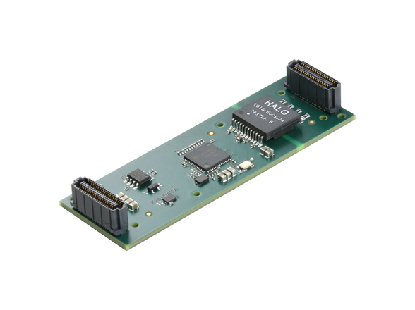
The XMC form factor provides up to 16 gigabit serial links. Let’s decide to use 8 for PCIe and 8 for Aurora. XMC carrier modules, such as Pentek’s Model 4207, can assist in preserving the VME investment while updating the system to VPX. The carrier contains a flexible crosspoint switch allowing the two XMC modules to be cascaded with one another.
A 3U VPX XMC carrier, such as the Model 5300 from Pentek, can then be used to implement the beamformer in a VPX system. A typical 3U VPX slot profile with multiple data paths is shown in the left side of Figure 2. (Some of these paths are referred to in the OpenVPX nomenclature as Control Plane, Data Plane, or Expansion Plane.)
To see how this relates to the beamforming application, consider that the setting of the weights and initialization of the system are considered Control Plane functions; the receiving of processed data by the host CPU is a Data Plane function; and the Aurora FPGA interconnection is an Expansion Plane function. Meanwhile, the right side of Figure 2 shows how nicely suited VPX is to the beamforming application.
Investment preserved
In our beamforming example, the bulk of the development of precision analog-to-digital conversion circuitry and the FPGA-based signal processing is in the XMC module. Using XMC modules comprising the sophisticated signal processing necessary for digital beamforming and then employing them on VME or VPX carriers is a smart way to keep a foot in both camps.
Pentek, Inc. 201-818-5900 www.pentek.com


