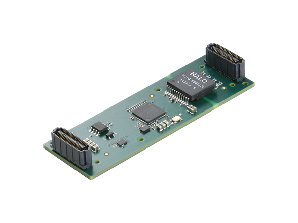
A very traditional engineering approach is to make a best estimate of the power requirements for each card in a system using whatever information is available, usually from vendor spec sheets. It is probably an exaggeration to call this guesswork, but not by much. Next, sum those requirements across all the cards and, finally, apply a safety factor. This “safe” number is then used to define the capacity of the system power supply.
During prototype system development and testing some voltages will be monitored, but a detailed evaluation of power consumption is unusual. As long as no problems arise, the initial power supply capacity definition will be retained.
While the traditional approach may be perceived as “safe,” there are a number of issues involved in its use. First, over-design of the power supply is a common result, with the degree of overdesign dependent on individual card estimates, the design engineer’s judgment, and the level of conservatism in the safety factor. Second, an overdesigned power supply will be physically larger and heavier than needed.
On large platforms like a naval vessel or manned aircraft, the incremental size and weight may be irrelevant. But on today’s smaller, unmanned platforms, unneeded size and weight has a negative effect on critical mission achievement parameters. And, on these small platforms the overdesign affects not only the computing system’s power design but also the power design for the platform, which must address allocating a limited supply across computing, communication, control, and other platform functions.
Moreover, it is possible to underdesign the power supply based on invalid card-level estimates. While underdesign will be discovered during prototype testing (assuming system tests match real-world operating demands), changing out the power supply will certainly have a negative impact on the development schedule.
Furthermore, during a system upgrade when a new card is being added or is replacing an older card, it is very difficult to know if the existing power supply will be able to support the change, given a lack of detail on both the current system’s power draw during operation and the power requirements of the new card.
While these issues are all widely recognized, the traditional “safe” design approach is still used, under the assumption that a detailed forecast of a system’s power requirements, under actual operating conditions, is simply not achievable. It is assumed simply too difficult to make accurate estimates of the power requirements for the complex, individual card-level system components. This is especially difficult for the current generation of modules built to the VPX standard, because the standard offers designers such a flexible array of voltage levels and power rail implementations.
The challenges involved in power estimation
Beyond the flexibility of the standard, there are a number of other factors that make estimating the power requirements of today’s VPX cards extremely difficult:
- Most VPX cards have a range of different configuration options in hardware. Processor clock speeds, memory sizes, and I/O interface options can all be selected from a range of choices, resulting in a large number of possible combinations. Card vendors have almost certainly not tested them all; in fact, some configurations may not even be built as prototypes before the first customer order.
- FPGAs, GPGPUs, and other configurable processing devices can have huge differences in power requirements based on different firmware loads and use profiles. It is simply not possible to know what the power draw will be without knowing how the device will be used during actual operations.
- Multicore CPUs will display a range of power requirements based on variations in software use across the cores. Again, actual power draw depends on device use during operations.
Power measurement using VPX intelligent extender cards
While advances in processing technology have made power requirement estimation increasingly difficult, another technology advance has given system designers the option of dispensing with estimation, and all its inherent problems, by moving to direct measurement of power use.
VPX intelligent extender cards, with built-in current and voltage monitoring, are now being used to accurately measure the power use of VPX modules as they operate in test systems. An intelligent extender card attaches to a card-under-test while it is inserted and functioning in a VPX system chassis. The operational firmware and software can be loaded onto the card-under-test and then operations initiated that simulate, as closely as possible, real-world mission situations. The intelligent extender card collects comprehensive data on actual power use while the card-under-test is running as it would in the field. A detailed power profile can then be developed, across a range of firmware and software configurations, and during multiple mission simulation use cases, giving a very high level of visibility into power demands (see Figure 1).
For example, within an Intel Core i7-based SBC, the software activity will vary depending on the number of i7 cores being used for different parts of the software deployment model. The effect of the variation in software use on power requirements can be captured and analyzed by a power monitoring extender card. Similarly, a PMC/XMC carrier module can be tested with different PMC/XMC modules so the variations in power draw are understood. Or, an FPGA card can be run with all the various firmware loads that may be required for different stages of a mission. For all these situations, an intelligent card extender with current and voltage measurement will capture the related changes in power requirements.
An available solution
Dawn VME Products has brought to market a leading implementation of this capability in the EXB-7458 VPX 6U Extender Board. Dawn’s embedded Rugged System Health Monitor (RuSH) technology provides the embedded intelligence which enables monitoring of critical system parameters on the card-under-test, including voltage, current, and control of power shutdown of all VPX voltage rails (see Figure 2).
This Dawn extender card fits enclosures designed for either .8" or 1" pitch boards. It can be used to quickly and easily measure and profile the normal current used on each voltage rail (see Table 1). The EXB-7458 will monitor six channels of voltage and six channels of current simultaneously and is designed to support the maximums allowed by the VPX specification. 3U VPX versions of this technology are also available from Dawn.
Multiple features are present to enable a testing environment that is both safe and productive (see Table 1). Thresholds can be set to instantly shut off power on any voltage rail should current limits be exceeded by any card-under-test, effectively protecting both the card and system from damage caused by short circuits. Switches and I/O connectors provided for On/Off, System Reset, LCD Display, Fans, and Serial Communications. There is also support for a remote cooling fan.
Summary
A comprehensive understanding of the power requirements for individual VPX cards is critical to designing power supplies for VPX systems. Advances in processing technologies and the growing flexibility in configurations have made accurate power estimation virtually impossible. However, intelligent power monitoring extender card technology has replaced estimation with the ability to develop detailed power profiles for cards-under-test while operating in simulations of real-world missions. By replacing estimations with empirical data, intelligent extender cards enable power designs that are both safe and optimized for mission performance.
Dawn VME Products 510-657-4444 www.dawnvme.com


