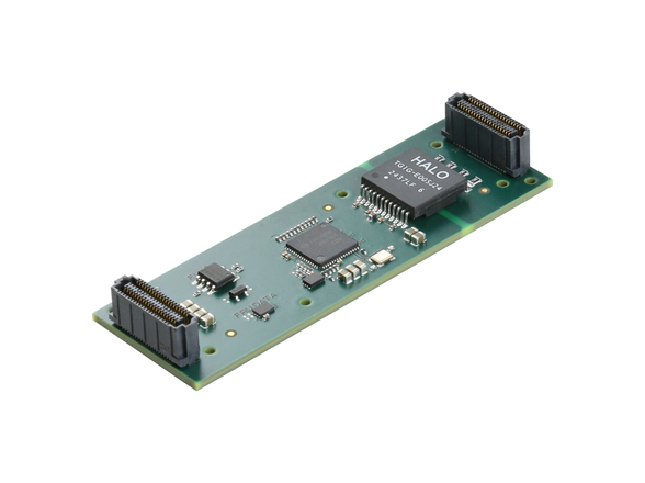
The FMC specification is currently the most frequently downloaded specification in the inventory of nearly 100 VITA specifications. FMC is very popular in many computer market segments that use FPGA technology. The FMC Marketing Alliance, formed in 2010, has more than 20 members that supply either FMCs or FMC carriers in several different form factors. Many more are not officially registered with the FMC Marketing Alliance.
Late in 2014, the effort to update the specification was started. The VITA 57 working group set out to: 1) extend the VITA 57.1 FMC specification to handle up to 32 Gbps to 28 Gbps transceivers on a single module, and 2) maintain backward compatibility between the new and old technologies in line with VITA tradition. Initially, the effort focused on the first priority and started a new working group under the VITA 84 working group, but feedback demanding that backward compatibility be maintained redirected the working group to be named VITA 57.4 so that this focus would not be lost. Suppliers and users alike clearly wanted the ability to plug a VITA 57.1 FMC into a new VITA 57.4 carrier.
Xilinx took the lead in developing the VITA 57.4 specification. Several proposals were made for achieving the working group’s goals of performance and backward capability. The popularity of FMC led to an abundance of prominent ideas from suppliers and users alike. Members spent much of the first weeks discussing the pros and cons of each of the proposals. The group also was quick to adopt the naming convention of FMC+ to identify their new work.
Samtec compared several configurations of the SeaRay connector system used in ANSI/VITA 57.1. To incorporate the additional pins needed for VITA 57.4, Samtec studied 12×40, 14×40, 16×40, and 18×40 pin layouts. The company determined that the 14×40 socket would be most practical, as it would accept the original 10×40 connector and the new 14×40 connector. It would also share contacts and signal integrity characteristics with the existing system.
An optional 4×20 pin auxiliary connector was part of the original proposal. This connector would extend support beyond 24 GTs to 32 GTs. The working group was concerned about the exact placement of the proposed auxiliary connector on an FMC. Space is very limited, and cooling is constrained. For carrier cards the location of the auxiliary connector would be right in the middle of the highest-density area of signal routing related to the FMC site. Keeping the auxiliary connector to one side of the other would minimize congestion near the primary connector. If the auxiliary connector was put on the front side of the main connector, then signal routing could potentially avoid interfering as high-speed routes could go around the primary main connector on the carrier card. The FMC itself has more flexibility, as it only has to route the signals that it needs, usually not all of the SERDES and all LVDS signals.
Other concerns discussed by the working group included reduction of the thermal interface of the wider connector. A more serious concern was raised about the impact of shock and vibration on the smaller auxiliary connector due to the weaker retention force of small size.
As of the time of this writing, the working group is still discussing pinouts. HiTech Global has also been performing layout analysis, which is being used to guide refinements to the final pinouts of the specification.
Summary of FMC+ VITA 57.4
The VITA 57.4 FMC standard extends the original VITA 57.1 FMC standard by specifying two new connectors that enable additional gigabit transceiver interfaces that run at up to 28 Gbps and eventually 32 Gbps. It also describes FMC+ I/O modules and introduces an electromechanical standard that creates a low overhead protocol bridge between the front panel I/O on the mezzanine module and an FPGA processing device on the carrier card that accepts the mezzanine module.


