VNX, also known as VITA 74, is defined in a specification managed by the VITA Standards Organization. VNX is now in its third and final year of “trial use” status and is on its way to becoming a fully ANSI accredited document.
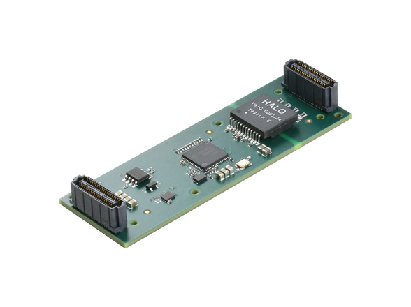
To date, the VITA 74 specification has seen no issues that would cause changes to be made to the baseline document. The biggest reason for this smooth sailing is that VNX is derived from other mature specifications. VPX (VITA 46) is the electrical parent of VNX. VITA 57, the FMC specification, provides the proven connector for the modules. Additionally, the 19 mm VNX module size and electronic design was chosen to optionally accommodate a PICMG COM Express Mini (Type 10) card.
The goal for the VNX specification is to take the concepts that have made VPX successful and apply them to a similarly architected small form factor platform, as well as to use other successful standards for connectors, connectivity, and form factors to specifically reduce development risk and time to market. The following discussion will compare and contrast VNX and VPX with respect to size, weight, power, and cost, also known as SWaP-C.
Size
To gain an idea of the size reduction for VNX in relation to VPX, Figure 1 shows the volume of various VNX and VPX modules. In the graph, the volume of a 19 mm module is normalized to represent 1.0 and contrasted against the other VNX and VPX module volumes. A 6U 1" pitch VPX card is nearly 8x larger than a 19 mm VNX module. The 3U VPX family is roughly 58 percent smaller than its 6U cousin, while the 19 mm VNX module is about 70 percent smaller than the 3U 1" pitch VPX module.
Weight
System size and weight are dependent on a number of factors, including number of slots, power supplies, and applied cooling techniques. With wedge locks and conductive plates, 6U VPX conduction-cooled SBCs can weigh in at approximately 4 pounds, excluding the one or two XMC modules, which can be provisioned. A typical 7-slot 6U VPX 1 ATR mission computer can easily weigh in at 40-50 pounds. The same class of ruggedization for a 3U VPX SBC will weigh between 1.5 and 2 pounds. A conduction-cooled 5-slot 3U VPX ½ ATR Short system with payload modules will weigh between 18 and 25 pounds.
By contrast, a 19 mm VNX SBC weighs about 8 ounces, and a fully loaded VNX system with four 19 mm slots and one 12.5 mm slot comes in at less than 7 pounds. In smaller airframes and vehicles where size and weight are important decision factors, the VNX size and underlying VPX technology make it an attractive solution for a growing number of applications.
Power
As with size and weight, power is highly dependent upon the number and types of cards in the system. For the purpose of this article, examples of SBCs, FPGAs, and graphics card power envelopes will be discussed.
The small form factor of VNX modules drives the standard to employ system-on-chip (SoC) processors whenever practical, as the SoC device will typically be using less power than its multi-chip cousins. The 6U VPX maximum power per slot is rated at 115 W using a 5 V supply, and 348 W using a 12 V supply. The 3U VPX maximum power per slot is rated at 115 W using a 5 V supply, and 276 W using a 12 V supply. While this is useful for certain compute-intensive applications, a 5-slot ATR chassis with a nearly 2 kW dissipation is beyond many platform power budgets and from a cooling perspective, is difficult to keep within the operating temperature range. Very few functions aboard an airframe or land vehicle require this kind of compute power.
The 12.5 mm VNX module is conservatively rated at 10 W, and the 19 mm module is currently rated for 20 W. In practice with improved mechanical design, proper operation has been verified at 15 W and 30 W, respectively, with no issues over the full extended temperature range. This results in a 5-slot VNX system, with four 19 mm slots and one 12.5 mm slot, potentially dissipating 135 W, not including power supply losses. In many cases, reduced weight and power dissipation may permit longer missions.
Cost
Connectors and metalwork in the form of wedge locks, front panels, and custom heat frames and REDI-covers are a substantial cost driver in both 3U and 6U VPX modules. The VNX module defined in the base specification eliminates a substantial portion of the metalwork and does not use wedge locks. The 12.5 mm module uses a single 200-pin connector, while the 19 mm module uses a single 400-pin connector. Driving VNX module cost down, the connectors are significantly less expensive than the MultiGig RT-2 connectors used with VPX, and there is a single connector, not multiple supplier-specific connectors. At the system level, since small form factor applications typically require less power, the resulting cost for power supplies is lower as well.
Signaling
As VNX is a direct derivative of VPX, the signaling on the VPX backplane looks and feels like a VNX backplane. In VNX there are planes for utility, management and control, data, expansion, and a user space, with similar numbers of signals as 3U VPX (see Figure 2).
Optimized for SWaP
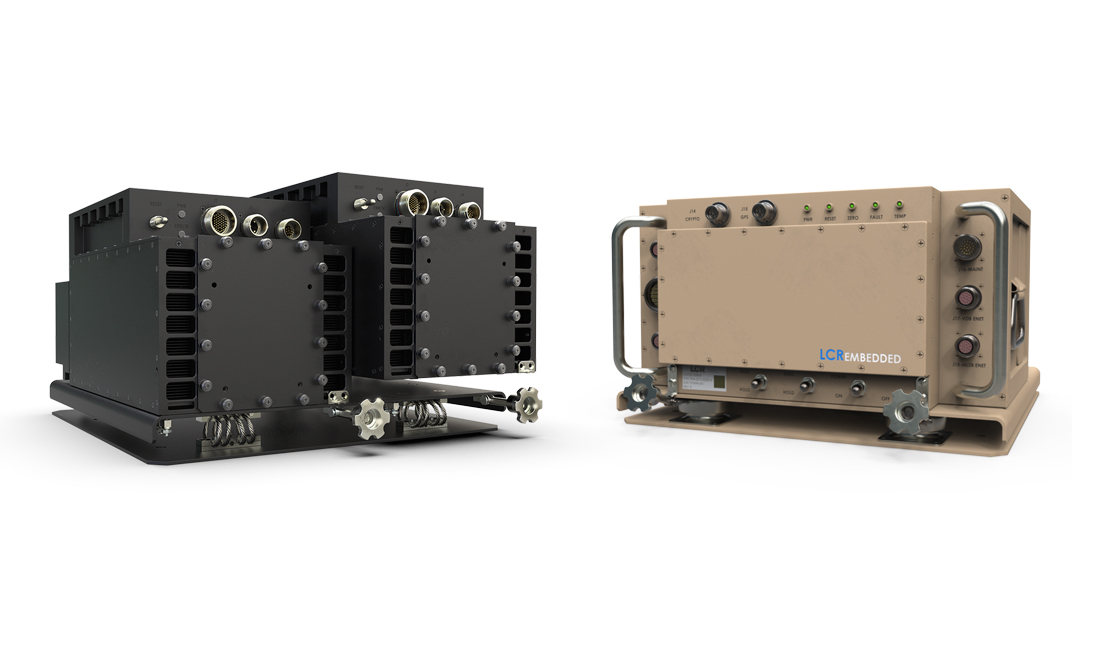
While a few applications require massive compute capabilities, many system functions on air and ground vehicles do not require the large amounts of compute power and performance that a full-up VPX solution is capable of providing. In these applications, VNX allows the system architect the ability to seamlessly provide well-understood VPX technology that has been compressed to a fraction of the space, stripped of excess weight, and implemented using enough processing power to get the job done. Using VNX, it is much easier to find a location in a cramped vehicle to put a system that has been optimized for SWaP. Figure 3 shows a 3U VPX system alongside its VNX equivalent.
Commercially, today’s system providers can now offer lower competitive pricing for applications where there is not enough budget to afford the advanced capabilities provided by yesterday’s systems. Today’s requirements can often be met by deploying systems that utilize and apply modern VNX technology for applications that would have been neglected due to the customer’s small wallet.
Creative Electronic Systems [email protected] [email protected] www.ces-swap.com


