
The data rates of serial switched fabric protocols used for OpenVPX slot-to-slot interconnect planes’ have increased from Gen1 (3+ Gbaud) through Gen2 (6+ Gbaud) and now to Gen3 (10+ Gbaud), with Gen4 (16 Gbaud) and Gen5 (25+ Gbaud) just around the corner (Table 1). At the same time some critical types system I/O have transitioned to high speed serial at similar baud rates.
Historically, rugged deployed system units (e.g. ATR boxes) have routed I/O signals using traces on backplanes and I/O panels, but this has become increasingly difficult, as baud rates have increased.
What happens when the multi-gigabit I/O baud rate goes up?
For high speed serial signaling, the Insertion Loss (IL) at the Nyquist frequency (one-half of the baud rate) is the first thing to look at. Although IL is merely one of several important signal integrity parameters, if we have too much end-end loss in the channel we have already lost the battle because there is virtually nothing left of the original signal! Commonly used OpenVPX Gen3 fabrics’ Nyquist frequencies range from 4.0 GHz to 5.15625 GHz for various protocols, while Gen4 fabrics’ Nyquist frequencies go up, ranging from 6.0 GHz to 8.0 GHz. When the baud rate and Nyquist frequency go up, the corresponding IL increases, so things get a lot worse.
OpenVPX rugged deployed system units often have I/O traces spanning 12 to 18 inches to get from backplane connectors to the external rugged I/O connectors. Because signal traces are very small conductors, IL for these long traces is significant, and it continues increasing as serial I/O baud rates and corresponding signal frequencies go up. For today’s multi-gigabit I/O, these high trace losses can spell disaster!
Solving the multi-gigabit I/O trace loss problem for rugged OpenVPX systems
I/O trace losses for today’s multi-gigabit I/O are simply too high, so a lower loss alternative is needed instead of the traces (Figure 1). Fortunately, cables have dramatically lower loss than traces, so a rugged cable solution is an obvious alternative.
Each fabric type has a budget for worst-case channel characteristics, so there is a maximum end-end IL budget at Nyquist for each fabric type and baud rate. Let’s take PCI Express (PCIe) as an example.
At PCIe Gen3 baud rate of 8.0 Gbaud, the channel IL budget at Nyquist (4 GHz) is 22 dB. A typical 12" low loss trace at Nyquist (4 GHz) has an IL of approximately -5 dB, or 23 percent of the total channel budget; 18" traces would consume 50 percent more, or 34 percent of the total channel budget. At Gen3 speeds, these I/O trace losses are large enough to cause serious problems when interconnecting two similar units. A typical 18" low loss cable at Nyquist (4 GHz) has IL of approximately -0.75 dB, or three percent of the total channel budget. This is more like it!
Moving to PCIe Gen4 with a baud rate of 16.0 Gbaud, the channel IL budget at Nyquist (8 GHz) is 23.5 dB. A typical 12" low loss trace at Nyquist (8 GHz) has an IL of approximately -10 dB, or 39 percent of the total channel budget; 18" traces would consume 50 percent more, or 59 percent of the total channel budget! At Gen4 speeds, these I/O trace losses are large enough to cause catastrophic problems when interconnecting two similar units. A typical 18" low loss cable at Nyquist (8 GHz) has an IL of approximately -1.5 dB, or six percent of the total channel budget. This is more like it!
We would argue that a reasonable system level loss budget target would be:
- 15 percent for each VPX module (x2 to cover both ends). This is consistent with ANSI/VITA 68.1.
- 10 percent for each VPX chassis from backplane slot to I/O connector (x2 to cover both ends)
- 50 percent for external I/O cable between the two ATR’s
The insertion loss of I/O traces is already a serious issue at current PCIe Gen3 rates, and will become a catastrophic problem at PCIe Gen4 rates (Figure 2). Each switched serial fabric has slightly different baud rates and budgets, but you can expect similar results. The I/O signal loss problem can be addressed by either significantly reducing the I/O signal loss, or by adding active devices (repeaters/re-timers) close to the I/O connectors to restore signal integrity.
Development and demonstration using VPX+ cabling system
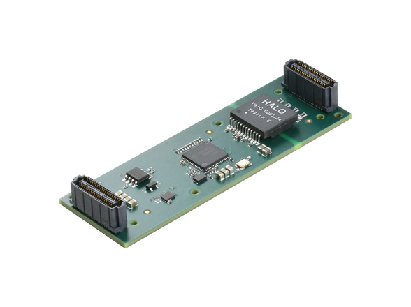
Replacing long I/O traces with rugged cables can solve the loss problem, avoiding the need for active devices to restore signal integrity. In OpenVPX applications, an excellent approach for Gen3 rates and higher is to utilize Meritec’s VPX+ cabling system for development and VPX+ DA (Direct Attach) cabling system for deployment.
The VPX+ cabling system has been used in many development systems. It effectively mates with standard OpenVPX backplane rear transition module (RTM) connectors. It can be used for slot-slot connections as well as for I/O connections, supporting custom slot-slot interconnects and often avoiding the need for custom backplanes in development applications. VPX+ is used with commercially available development backplanes in many applications, because extra signals can be easily added with the VPX+ cables. A shock and vibration test report is available from Meritec.
The VPX+ cabling system enables rapid evolution from development systems to demonstration systems (Figure 3). Optional deployment rails provide additional strain relief for more rugged applications.
Rugged deployment using VPX+ DA (Direct Attach) cabling system
Deployed platforms require a more rugged solution. Meritec’s VPX+ DA cabling system is the preferred approach for rapidly transitioning demonstration systems to moderately rugged applications such as air-cooled rack-mount platforms. VPX+ DA eliminates backplane RTM connectors that are used with VPX+, saving cost and improving performance. It can be easily dropped in to replace VPX+ cabling.
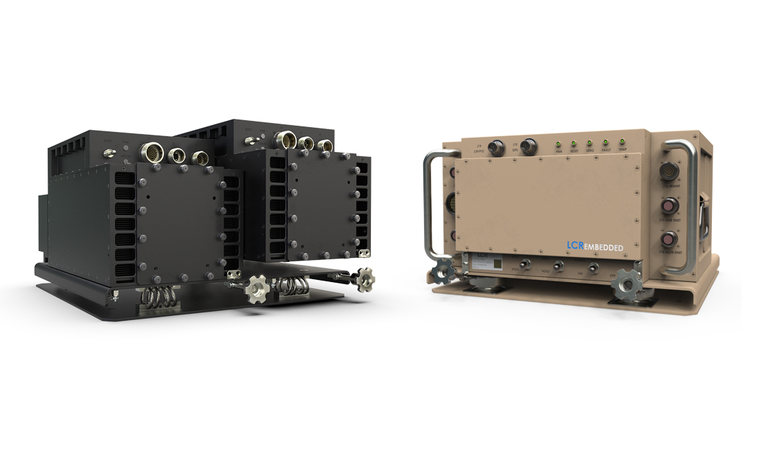
VPX+ DA press-fits directly into OpenVPX backplane connector holes, in place of backplane RTM connectors. The press fit connection is lower in cost, more rugged than VPX+ and with improved signal integrity performance. In highly rugged systems such as conduction cooled ATRs the VPX+ DA offers other benefits. Its low profile is suitable for space-constrained or rugged conduction cooled applications such as ATRs (Figure 4). VPX+ DA can be used for some or all of the I/O signals and it can be combined with other I/O strategies such as I/O panels.
For development and demonstration applications, VPX+ cabling is a good solution for multi-gigabit OpenVPX I/O and custom slot-slot backplane interconnect in lieu of using one or more RTMs.
For rugged deployment applications, VPX+ DA cabling is the rugged solution to solve trace loss issues for today’s newest multi-gigabit OpenVPX I/O. As compared to VPX+ cabling, VPX+ DA cabling directly replaces both the RTM backplane connectors and mating VPX+ connectors for both cost and weight reduction while realizing increased performance.