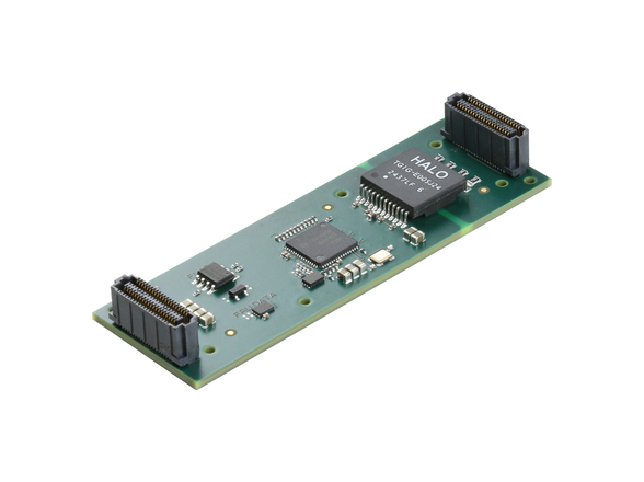
Two key elements stand out in SFF designs. The first is modularity, which implies flexibility, expandability and configurability. To the end user, it means repurposing or upgrading equipment over its service life while maintaining the existing system footprint and preserving as much of the initial investment as possible. The second element is NRE: In an industry where NRE is the bane of designers – and many times a necessity for suppliers – economy dictates that modularity must equate to lower-cost quotes for NRE, or none at all.
The key to moving towards these demands? Paying attention to the details in SFF system designs, which incorporate widely available modular board solutions.
Why modular matters
In the defense embedded business, smaller is nearly always better. Air, sea, and land vehicles are space-starved environments, so good SFF system designs must start with the primary goal of designing systems that are either as small as possible or in sync with the de facto size and footprint expectation for a certain application.
In this context, the definition of SFF systems refers to non-slot card architectures, although in some cases, 3U slot cards may certainly be used in “small” systems.
Keeping in step with emerging applications, most traditional suppliers of VITA and PICMG Eurocard-based 19-inch rackmount equipment are increasingly being drawn into the SFF realm, which is currently dominated by COM Express and PCIe/104 board payload types and their many variants.
In terms of form factors, the basic ingredients of a modular SFF system tends to have evolved into a mix of the following:
- COM Express: CPU
- PCIe/104 variants: CPU or I/O
- miniPCIe: I/O
- M.2 and mSATA: data storage
- XMC/PMC: specialized I/O
Rugged modules signal new capabilities
The development of rugged modules is a huge enabler to the “modularity” mantra now pervasive in SFF systems. As end-use applications continue to demand that increasing technical capabilities be packed into ever-shrinking spaces, embedded systems developers are drawn to SFF solutions. In response, the newly available rugged modules are finding homes in systems used in harsh and unforgiving environments.
COM Express modules, while they hail from the commercial realm, are widely used in defense applications. They are now seen as viable computing solutions, thanks to the use of long-life-cycle CPUs and leading-edge rugged extended-temperature versions. MiniPCIe cards have been around since 2005 in the PC industry, with M.2 and mSATA form factors also emerging from the PC world. Extended-temperature versions are now available in all three categories. For their part, PCIe/104 and XMC modules have an established history of proven performance in rugged environments, so they’re also a natural fit for the rugged modular paradigm.
Extended function of carrier cards
Historically, the carrier card for a COM Express board merely served as the break-out vehicle for native CPU I/O: USB, Ethernet, video, audio, SATA, etc. Carriers were seldom larger than the COM Express module itself, which served the I/O needs of the commercial application space quite well.
Advancing from parallel to serial connectivity, and the resulting proliferation of high-speed PCIe serial I/O ports on CPUs, gave rise to a whole new range of I/O possibilities. The move boosted the workload expectations of the carrier card. In response, MiniPCIe manufacturers brought out a range of converter modules addressing Gigabit Ethernet, GPS, CAN bus, ARINC, Wifi, a variety of video, and so on. Carrier card designs became larger and more complex to include sites for miniPCIe modules, which converted PCIe to the target I/O for the new applications that opened up as a result.
A natural extension to the added functionality in SFF systems is the need for onboard data storage, which means that carrier sites are common for mSATA and M.2 SSDs modules, with capacities now in the terabytes. XMCs are necessary when considering specialized expansion for FPGAs and frame grabbers. In addition, PCIe/104 and COM Express modules now coexist in the same neighborhoods, thanks to creative suppliers who leverage the benefits of both, combining their respective capabilities onto a common carrier.
This evolution has led to highly capable SFF systems sporting the latest CPUs with high-speed application-specific I/O and multiterabyte data storage. Cap off these systems with rugged power supplies and custom I/O panels in solid packaging and suddenly there’s a clear path to an emerging selection of full-featured, configurable SFF platforms. (Figure 1.)
Successfully bringing modular SFFs to market
Successfully integrating, packaging, and qualifying SFF systems that incorporate application-specific computing and I/O recipes is a topic unto itself. Instead, let’s focus on the nuances of going to market with SFF systems given the expectations of modularity and NRE, as discussed earlier.
SFF board architectures lack a strong set of governing standards that apply to the external packaging. Given the nature and variety of the applications and varying size requirements, nailing down a standard with a lot of coverage may prove impossible.
Several standards have been floated by VITA, however none have gained wide acceptance yet. As a result, the size and shape of the enclosure as well as the connector selection and pinouts in SFF systems change from application to application. By contrast, in slot card-based systems, 19-inch rackmount chassis are well defined by size standards, as are ATR [air transport rack] chassis size variants.
Regarding connectors, external connections in air-cooled 19-inch chassis are typically cabled off native payload board connectors, then supported in downstream equipment. While external connections are integral to ATRs and other fully enclosed chassis, market expectations in these traditional Eurocard-based systems are that the connector arrangement and I/O panel design is generally custom. This custom expectation regarding connectors and I/O panels must carry over to SFF systems.
Almost off-the-shelf
For end users and suppliers, predefined off-the-shelf SFF systems that fulfill the needs of the application represent the path of least resistance – the holy grail. The intent is that an off-the-shelf solution will address the requirement with minimal to no customization, but this is rarely the case. Understanding this goal, many suppliers offer productized off-the-shelf, fully-defined systems that are either designed for the general market from the start or are driven by specific customer requirements and later productized for the general market.
The latter case leverages the value of an existing design for use in future applications, while the former represents an educated guess. Either way, one thing is certain: The off-the-shelf product will require some level of customization before it can fully address the next opportunity. Some aspect of the design will need to change, whether it’s the I/O recipe, CPU, port count, I/O panel configuration, outer dimensions, or the like.
In SFF systems, this is the reality. The question is how to implement the new requirements and keep the cost, response time, and lead-time expectations of the market in alignment with the design.
Bridging gaps in design requirements
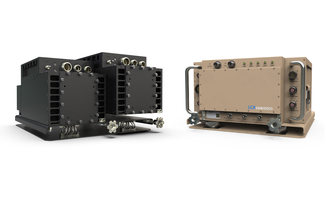
Initial inquiries into an off-the-shelf SFF system usually begin with a list of required features, which are not apparent in the system being considered. It often sounds like: “The ComSys seems to fit our requirements however …” It’s the old “COTS, but …” conversation. (Figure 2.)
Even application-ready SFF systems, like Elma’s rugged ComSys, will incorporate an element of configuration to accommodate evolving mission requirements and component obsolescence.
The discussion that follows the choice of a system determines how quickly the need at hand can be addressed. Streamlining and shortening the bridge between what’s being offered and what’s needed is a measure of a successful baseline design. The shorter that gap, the better the initial design.
Because they’re configurable, modular SFF systems can be marketed and offered with predefined I/O recipes for various applications. Recipes may address communications-centric usage, mobile applications, compute-centric, mission-control-centric, or mobile networking in air, land, and sea. Well-designed systems enable end users to see the utility not only in the specific configuration of the system, but just as importantly, in the configurability of the system. It’s important that suppliers can articulate the latter point. Carrier design and a holistic system-design approach facilitate change both at initial definition as well as further down the line after deployment.
Carriers design for mission evolution
Missions change, I/O requirements evolve, and CPUs run out of steam during the lifetime of a system, so optimal carrier design is paramount when it comes to accommodating those changes. In addition to the COM Express CPU module, carrier designs should support between one and four miniPCIe sites for application-specific I/O. Intelligent designs, which include stacked sites, allow a rich set of I/O without increasing the footprint of the system. An important goal of the design is to support as many I/O recipes as effectively as possible. MiniPCIe enables this and leaves open the possibility of changes at a later date.
Modular designs should enable system upgrades while preserving as much as possible of the total initial cost of the system. Accommodating storage and specialized I/O with M.2/mSATA and PMC/XMC sites, respectively, further enable downstream configuration changes.
With I/O changes come I/O panel design variants: Commonly-used connectors include MIL-DTL-38999, Mighty Mouse, and M12 connectors, which come with their own array of options. Rugged systems are typically cableless designs, in terms of internal connectivity. The I/O panel, therefore, includes not only the connectors, but also the underlying PC board and the front face of the enclosure. Even as system changes are accommodated by the modular design, NRE charges when necessary are often related to getting the signals outside the box.
Robust and well-rounded modular designs
Capping off a successful modular design and further shortening the “however” discussion is the designer’s ideal expectation. Experienced embedded systems suppliers will help with qualification testing for a series of anticipated designs. They also should bring to the table extensive thermal and functional testing of multiple configurations derived from the system in question as well as from other similar systems from their overall offering.
Well-engineered modular SFF system designs should allow for streamlined configuration changes in order to maintain optimal performance, while minimizing the time and cost associated with those changes. Smart designs will include support for a balanced mix of I/O recipes, computing options, and storage upgrades in the form of COTS modular board form factors. Suppliers with experience in designing custom packaging for harsh environments are best equipped to offer a complete solution across multiple applications.
Elma Electronic www.elma.com


