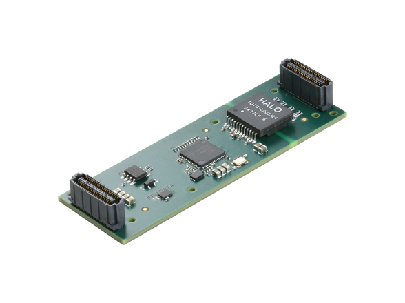
It has been several years since the introduction of a new mezzanine form factor for low-profile applications. The VITA membership has been doing some soul-searching to determine what should be next. Plenty of controversy is in the air, with everything from simple right-angle edge connections and optical links to the carrier being thrown into the fray.
Standards for mezzanine boards were among the first to be ratified by VITA members and ANSI when VITA first gained ANSI accreditations status in 1993. Since the inception of VMEbus, there was always a need for mezzanine boards to add functionality to 3U and 6U VME boards. There was never enough board space for all the needed functionality, plus there was the added challenge of very limited z-axis space on a VME board. Early board designers created their own custom mezzanines to add memory, I/O, or processing capability. Unfortunately, it also meant that most of this work was unique to every company designing boards.
It didn’t take long before industry players started developing standards to address the need for interchangeable mezzanine modules. Over time, PMC, XMC, and FMC emerged to be the primary solution, that have carried into the world of VPX. While the form factors are still highly desirable, the performance of the interconnect has had to improve, often at the cost of different connector technology. There is no sign that this will subside anytime in the near future.
This situation has introduced the “mezzanine madness” dilemma that is challenging the standards working groups, and has led to a resurgence in efforts to introduce change to the popular VITA mezzanine standards.
At the September VITA standards meeting, David Givens, standards director at Samtec, launched into a discussion of this mezzanine madness. If you have never seen a presentation by David, you are missing out! He has a colorful way, almost musical, with words that must be heard to be appreciated. His presentations alone are often worth the price of admission.
David’s view on mezzanines is that of a connector supplier, where he describes connectors as “the mortar between the bricks” or the boards in a system. He led off his mezzanine madness discussion with the question “What are we studying here?” Depending on your perspective – as either a board designer or a connector supplier – might answer the following way:
Board designer
- Lossy lumps of dielectric filled with temperamental conductors.
- Highest failure-mode component on my board.
- Nightmare-inducing electromechanical demons.
Connector supplier
- Critical disconnect points in a modular electrical system.
- Passive components that determine the form, fit, and function of modern packaged electronics.
VITA standards define two mezzanine families, XMC and FMC, that are used in computer designs over a broad range of products. Both have served designers well for years, supporting escalating signal demands that have consumed surplus headroom. Both have different requirements driving their strategy, however: XMC technology is driven by serial communication protocols such as Ethernet and PCIe, while FMC is driven by FPGA requirements that have growing bandwidth needs.
PCIe moved from Gen 1 to Gen 5 in 16 years; PCIe’s roadmap continues to squeeze more bandwidth out of each generation. FMC needed more bandwidth, so the standard defined a higher pin-count connector, moving from 800 pins for FMC to 1,280 pins in FMC+. (Figure 1.)
|
|
Pin-in-socket connectors drove the industry for several decades, but blade and beam contacts are now used on both the backplane and mezzanines. Their acceptance has been driven by the critical need for higher pin density and proven signal-integrity (SI) advantages.
SI requirements and hardware trends imply that next generations will drive upgrades in PCB materials, layout techniques, and an emphasis on channel integrity, not just signal integrity. Designers will need to spend more time considering the most innate details of every single signal trace. Ultimately, on-chip equalization will ease some pressure on connectors, but new Gen 3 standards for XMC and FMC will be needed. The new standards will be optimized even more for high-speed, high-density channels with low crosstalk. SI engineers will soon be spending a disproportionate amount of time on designs getting clean signals.
VITA has several active working group projects:
- VITA 42.0 – XMC: The working group has opened up the standard to make some minor revisions to performance tables and possibly add information at about standoffs that define mounting to a carrier board.
- VITA 42.3 – XMC PCIe Physical Layer: This version does not support applications above PCIe Gen 2 performance capability. Other inputs that have been collected over the past few years need to be considered. This work group is at present updating the standard to support designs up to PCIe Gen 5.
- VITA 57.1 – FMC and VITA 57.4 – FMC+: Minor errata have been reviewed and approved for release to address questions with dimensional concerns and image quality.
- VITA 57.5 – FMC+ Development Tools: Three application notes have been completed and posted:
- JSOM Ejector Standoffs for VITA Mezzanines.
- FMC+ Extension Cables for benchtop development.
- FMC+ Loopback Cards for system testing and development.
These notes are targeted at developers to aid in the design of FMCs and carriers.
- VITA 61.0 – XMC 2.0: Requires revisions similar to VITA 42.0 and VITA 42.3.
- VITA 88 – XMC+: The desire to bring XMC up to performance parity with FMC+ motivated members to form the VITA 88 working group. Here, the same connector family used in FMC/FMC+ can be soldered to the existing XMC footprint, offering backward compatibility in most applications. New layouts will benefit from an electrically optimized via-in-pad design, familiar to FMC+ developers. Universally, low mating/unmating forces and rugged IPC Class 3 solder joints will directly benefit all XMC+ users.
|
|
Deep thoughts
David closed his presentation with some thoughts about what we can conclude:
- Over time, new processors that employ evolving transmission protocols drive an increase in the system hardware.
- Periodically, technology upgrades converge to cause inflection points that require major redesigns. There is no choice but to bite the bullet and make wholesale changes. In an industry that is so specialized and moves at such a slow pace as critical embedded computing, changes such as this can be hard to embrace.
- The next “3.0 generation” of connectors is emerging into a full-channel SI challenge. New connector fundamentals are going to drive change: Footprints will be optimized, pin counts higher, tall stack heights avoided where possible, routing strategies may reduce rows. Anything that reduces noise and crosstalk will be an asset.
- We expect the entire ecosystem will need a thorough upgrade: High-performance PCB materials, active equalization (which may be on-chip), attention to trace and layout techniques, and full-channel budget management.
- V88 XMC+ gives backward-footprint compatibility with forward-looking electrical and mechanical benefits. (Figure 2, right.)
- The next generation … a completely new “VPX 3.0” architecture? Maybe the day for “drop-in” improvements is at its end.
Now is the perfect time to get involved if you are concerned about the future of mezzanine standards for low-profile carrier boards. In order to move to the next level, we know that changes are required and standards are going to be needed.


