For more than 25 years, the VME architecture defined COTS systems that met the demand for increases in computing and connectivity. Successive generations of new processors provided more and more compute cycles, while VME bandwidth evolved in a similar fashion from 40 MBps on the original VMEbus to 80 MBps, then 160 MBps, and finally 320 MBps on double-edged source-synchronous transfer.
In its familiar 6U form factor, VME found its way into small 6-slot chassis and large 21-slot systems, as well as many ATR and half-ATR configurations. However, after an incredibly long run, the VME connector finally ran out of gas. As processors continued to get faster, it simply wasn’t possible to coax out any more bandwidth from the bus.
VITA addressed the need for a new generation of standards by pursuing two options. The first option, VXS (VITA 41) has a much higher bandwidth than VME, delivering up to 5 GBps to each payload slot, and also offers a large degree of backward compatibility at the module level. Because the bandwidth is delivered via a switch fabric such as Serial RapidIO, the overall performance impact is even greater.
The other new standard option is VPX (VITA 46), which was developed without the constraint of backward physical compatibility. VPX defines a multiplane architecture approach that provides support for very high-bandwidth communications. The standard delivers more than 10 GBps via a switch fabric to each payload slot over the data plane and equivalent bandwidths over an expansion plane using a point-to-point connection such as PCI Express.
After its initial definition, the VPX standard morphed into a family of specifications, often referred to as “dot specifications,” defining a number of board-level implementation options. The flexibility was nice but resulted in a situation with severe interoperability problems – modules developed by multiple manufacturers didn’t work together. Thus, OpenVPX (VITA 65) was developed to address this issue. Building on the VPX definitions, OpenVPX added the concepts of planes, pipes, and profiles to define an architecture framework for interoperability. OpenVPX is being adopted rapidly in new embedded designs; however, widespread use of VME means the standards will coexist for some period of time.
The need for hybrid backplanes
Despite its success in addressing application requirements, OpenVPX cannot instantaneously achieve the coverage breadth built up by VME over decades. On the financial side, proven VME modules represent significant investments. For example, current intelligence, surveillance, and reconnaissance programs are often challenged to combine data from different types of sensors in real time. Some sensor interfaces have already been developed and deployed on existing programs. Other interfaces are completely new. The goal is to use them all within one platform in an efficient and cost-effective manner.
Meeting this type of challenge sometimes requires the use of hybrid backplanes to bridge legacy technologies by bringing together heterogeneous backplane architectures such as fabric-based OpenVPX and legacy VME into a single system. A major advantage of a hybrid backplane is the ability to continue using specialized, existing hardware and thus preserve years of development and system cost.
OpenVPX lends itself to a hybrid backplane approach. It offers flexibility in terms of interconnects and topologies to mix and match with legacy boards, which enables integrators to custom-design the interconnects over a hybrid backplane to meet the application’s unique needs.
When hybrid backplanes make sense
Not every legacy application is a good candidate for a hybrid backplane solution. However, when key factors align, using a hybrid backplane can save a significant amount of time and money.
In many cases, recreating a custom-designed VME board as an OpenVPX module is cost prohibitive. Industry experience shows that spinning, testing, debugging, and respinning a new 6U board of moderate complexity will cost more than $1 million and require at least nine months, often more than a year, to complete. Alternatively, using a hybrid backplane, development time can be cut to three or four months with costs as low as $50,000. In addition, this approach lowers overall project risks by using proven technology for a specific function.
Hybrid backplanes are an optimal choice for a system upgrade in situations where (a) an existing legacy board performs a function that won’t cause a system bottleneck; and (b) a legacy board was highly customized for a specific purpose and can’t be replaced with a commercially available component.
Hybrid backplane challenges
Although customized hybrid backplanes can be attractive in many situations, they require design and manufacturing expertise to be implemented effectively. As a start, design engineers must determine how many slots are required; which subsidiary protocol each slot will support; which interconnection topology will be required from slot to slot; how communication between the modules will be managed; what voltages will be supported at each slot; and what slot(s), if any, will need rear transition modules. Physical spacing between the slots differs between standards, which must be accounted for in the design plan.
Establishing communication between legacy modules and new system components is a key function provided by a hybrid backplane. For example, communication between a VME slot and an OpenVPX slot involves customized connections between mapped pins on both types of connectors. On the OpenVPX side, the concept of profiles can be used to assist this mapping.
The OpenVPX standard defines a set of system architectures within VPX and provides a framework for interoperability between modules and backplanes. With OpenVPX, system integrators can more readily architect an application-specific system based on compatible OpenVPX profiles for modules, backplanes, and development chassis.
An OpenVPX backplane profile is a physical definition of a backplane implementation that includes details such as the number and type of slots that are implemented and the topologies used to interconnect them. Ultimately, a backplane profile is a description of channels and buses that interconnect slots and other physical entities in a backplane.
Reviewing the following two generalized hybrid backplane options will help show what is possible; however, a great number of variations could be implemented.
Hybrid backplane design approaches
OpenVPX bridge slot
A straightforward approach is to use an OpenVPX bridge slot. VITA 46.1, part of the VPX specification, maps the VMEbus interface directly onto specific VPX connector pins. A hybrid backplane connects the VMEbus signals from the pins in the VME slot to the defined pins in the OpenVPX bridge slot. The bridge module in this slot accepts the VME traffic and then routes it to a VPX-friendly interface – either the control plane (many recent VME applications use VMEbus for control) or the data plane.
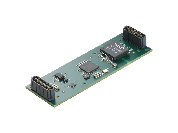
When a VITA 31 module is used, other considerations must be examined (Figure 1). Because VITA 31.1 is a full 1000BASE-T implementation and VPX utilizes a 1000-BX SERDES interface, a PHY conversion must be completed to interconnect the Ethernet interfaces. In a conduction-cooled embedded system, a specialized Active Interface Module (AIM) is often created to break out I/O. This conversion can be placed onto that module. The hybrid backplane must be laid out to make the connections from the P0 pins in the VITA 31.1 slot to the designated user-defined pins on the AIM. Note that a bandwidth mismatch exists from what would be available with VME (320 MBps) compared to 2 GbE at 250 MBps.
Map user-defined VME pins to OpenVPX connector
Another simple yet effective method for implementing a hybrid backplane is shown in Figure 2. User-defined pins in the VME P2 connector are mapped by the hybrid backplane onto selected VPX connector pins.
This approach can be used with a PMC or XMC I/O interface attached to the VME module, which brings the I/O down to P2 pins. The user can then implement a lower-speed serial protocol or another parallel interface. Depending on what is being implemented, this could connect to the VPX module’s data plane, control plane, expansion plane, or into the user I/O area.
Meeting unique requirements with a VME/OpenVPX hybrid backplane
Designing a hybrid backplane, mapping out communications, and defining and routing signals all require special skills. And, like most complex technical tasks, these activities are greatly aided by experience.
With careful planning and experienced system architecture design, custom hybrid backplanes can create a path forward for defense contractors. These backplanes help contractors evolve to next-generation technology while continuing to use critical legacy boards, thus minimizing costs, risks, and time to deployment.
Thomas Roberts is a solutions marketing manager at Mercury Computer Systems. He has more than 20 years of experience in systems engineering and technical marketing with IBM, Nixdorf, Data General, Digital Equipment, and Compaq. Tom has a BS in Engineering from Cornell University and an MBA from the University of Kansas. Contact him at [email protected].
Mercury Computer Systems 978-967-1291 www.mc.com


