Analog and Radio Frequency (RF) input and output is very common in critical and intelligent embedded systems. Providers of equipment use front panel connectors or customized coaxial backplane implementations for analog, video, and RF signals. Missing is a backplane standard that provides coaxial connectivity for RF, video, and other analog signals through Rear Transition Modules (RTMs). The need was particularly amplified during the development of the VPX standard.
Members of the VPX working group recognized the need and started an effort that led to the launching of the VITA 67 working group.
The motivation for coaxial connectivity on the backplane is driven by several factors, including:
- Quick disconnect and replacement of modules, providing lower Mean-Time-To-Repair (MTTR).
- Limited front panel space and access – conduction cooled VPX modules require that there be no front panel I/O.
- Improved modularity and scalability of complex architectures.
- Coaxial interconnects in modules can significantly improve isolation from interference and noise.
Consider a signal processing system that has many analog channels and clocks. In units with front-panel coaxial interfaces, it can take more than an hour to replace a card because of the need to disconnect and reconnect a complex rat’s nest of cables. With a rear-panel coaxial interface, the card can be replaced within one minute.
The VITA 67 standard was written to enable coaxial RF/analog interconnects to coexist on the backplane with VPX standards (see Figure 1). For instance, the rich capability of VPX serial interconnects can be integrated with the VITA 67 standard, including: Gigabit Ethernet, 10 Gb, InfiniBand, Serial RapidIO, PCI Express, and others. In many implementations, the maximum serial bandwidth of a VPX serial switched fabric is not limited, since the coaxial connector position on the backplane is strategically placed to enable the full capability of the defined VPX dot standards. In 3U implementation, the coaxial connector uses the same backplane connector positions as the ANSI/VITA 66 Fiber Optic Interconnect standard and thus limits the use of optical interconnects in the same 3U backplane position.
The significant differences between the VPX base standard and the ANSI/VITA 67 base standard are:
- Coaxial interface connectors are used in place of the differential digital connectors in the VPX P2 through P6 positions.
- Physical connectors can cross the standard P1 through P6 connector boundaries. This is useful when a coaxial module is not exactly the same size as standard RTM connectors.
A variety of backplane configurations are possible:
- Only ANSI/VITA 67 coaxial slots in a chassis.
- Both ANSI/VITA 67 coaxial and VPX slots in a chassis.
- ANSI/VITA 67 coaxial and VITA 66 Optical slots in a chassis.
- ANSI/VITA 67 coaxial, VITA 66 Optical, and VPX slots in a chassis.
In addition to a rich variety of backplane architectures, this standard enables a variety of coaxial connection configurations:
- Number of coaxial connectors in a module.
- Number of coaxial modules on the backplane.
- The combination of coaxial connectors, optical connectors, and discrete digital I/O on the backplane.
VITA 67 coaxial interconnect specifications
VITA 67 consists of a base specification (ANSI/VITA 67.0-2012) that details the nomenclature used in subsequent dot specifications. The dot specifications define suitable families of coaxial interconnect for use in VPX architectures. Two dot specifications have been ratified along with the base specification.
ANSI/VITA 67.1-2012 details the configuration and interconnect for a 3U VPX interface containing multi-position blind mate analog connectors with up to 4 SMPM contacts.
ANSI/VITA 67.2-2012 details the configuration and interconnect for a VPX interface containing multi-position blind mate analog connectors with up to 8 SMPM contacts each able to be located in positions P2/J2 to P6/J6.
The future
Feedback and technology improvements have lead the VITA 67 working group to research improvements to the earlier work, and several areas of improvement have been identified:
- Static daughter card interface – The floating SMPM contact on the daughter card has been an issue on multiple fronts. The movement makes using semi-rigid cables a risk and requires the use of flex cables. Flex cables are more expensive and they fall short of the performance capabilities of semi-rigid cables.
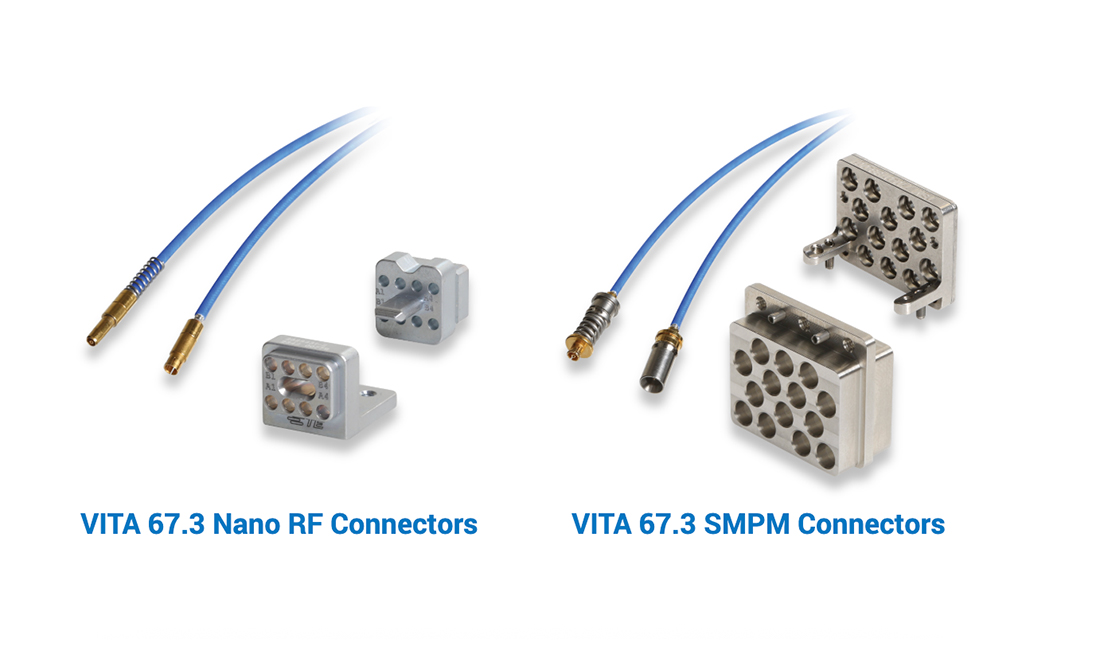
- Connector interfaces – The current VITA 67.x specifications were intended as a stepping stone to better arrangements. Today there remains a need for a connector on the rear of the backplane and for the cabling within a daughter card. VITA 67.3 hopes to eliminate both of these to improve performance, reliability, simplicity, space, and cost. Sprung contacts would be moved to the backplane. This gives more room for movement and allows larger diameter flex cable to be implemented for better performance. The change also eliminates a connector interface. System integration is less complicated because cables would become part of a payload card and treated as a system.
- Volume – The interfaces on both sides of the backplane require a relatively immense amount of space. Access is required to thread on the OSMM connectors on the backplane and allow an appropriate fan-out. Routing cables to another connector on the daughter card is very difficult and unnecessary. These two areas are optionally increased through the VITA 67.3 specification.
The working group is researching options for an interface compatible with VPX containing multi-position blind mate analog connectors with SMPM-style contacts with fixed contacts on the plug-in module and spring action on the backplane.
The driving principle is to allow fixed contacts on the plug-in module and spring loaded contact action on the backplane. This functionality allows for alternate packaging of the modules, potentially eliminating all cables on the plug-in module.
The work being done on VITA 67.3 has significant cost reduction, reliability, and serviceability benefits. For example:
- Connectors – The connector interface on the backplane is a source for multiple system headaches. Removing the interface on the backplane improves reliability. Cost is reduced by eliminating the need for another connector interface.
- Cables – Cables can either be completely removed or they can be static. This allows the use of semi-rigid cable for better and more stable performance. Not requiring exotic flex cables reduces lead time and cuts material and assembly costs.
- Chassis integration time – All cables are tested and provided by the card provider. The backplane module is treated as an assembly, reducing integration complexity and difficulty. All cables can still be replaced and serviced individually as required.
If you are interested in learning more, visit the VITA website at www.vita.com.

