With the 30- to 50-year life expectancy of typical military platforms such as airplanes, helicopters, armored vehicles, and ships, throughlife cost has become a much more significant factor than the initial capital procurement expenditure. Integrators and end users have identified that these operational and support costs could be reduced by 50 percent to 70 percent by streamlining the traditional three- and four-tier maintenance models. In turn, this will impact the construction and maintenance of both the platforms themselves and their electronics fit.
Traditional VMEbus and other COTS-based embedded computing solutions were initially designed to complement the three-level maintenance concepts then in vogue. The three services have basically similar maintenance philosophies, which can be illustrated by looking at the Air Force’s model:
- Organizational Level (O-level): Carried out as expeditiously as possible between missions of operational equipment. Includes assessment of battle damage, preventive maintenance, and inspections. Repair of electronic equipment is by Line Replaceable Unit (LRU), equivalent to complete box level replacement.
- Intermediate Level (I-level): Normally at a fixed facility allowing modules to be replaced and the LRUs to be fully tested before being returned to O-level. Modules are sent to the next lower level for repair.
- Depot Level (D-level): A specialized facility where individual modules can be repaired. In many cases, particularly for COTS products, the module’s manufacturer provides D-level repair.
The introduction of Line Replaceable Modules (LRMs) has revolutionized the infrastructure, logistics tail, and costs of electronics maintenance when compared with the three-level model. An LRM, which is generally similar in size and functionality to a VMEbus product, can be replaced at O-level and returned directly to its original manufacturer for repair. This reduces the number of fixed facilities and spare parts required, in addition to significantly reducing the cycle time of modules from broken-to-repaired and back into the field. LRMs are being used in newly designed platforms, most notably the F-22 Raptor and F-35 JSF and consideration for the FCS family of vehicles. The LRMs must be accommodated by the chassis and backplane, which become part of the vehicle structure. The cooling system is integral to the design of the platform, and quick release panels provide access to the LRMs for rapid replacement in the field.
LRM characteristics
Through many years of experience, the military embedded computing industry has demonstrated that the optimum module size for performance, ruggedness, and power dissipation tends to the 6U form factor. Many programs have also benefited from the use of VME or CompactPCI to create their ideal solutions. The LRMs for military applications have a number of desirable characteristics that can be built around the strengths of COTS and the 6U form factor, as outlined in Table 1.
|
Desirable LRM characteristics |
Rationale |
Compatibility with VME |
|
ESD protection |
An LRM will be handled by a maintainer in the same way as a complete boxed system, without the use of any ESD precautions. |
Although a number of proprietary solutions have been offered, current connectors offer no ESD protection during handling. New VPX (VITA 46) connectors will provide ESD protection. Top and bottom covers are standardized in VPX-REDI (VITA 48) to protect the complete assembly. |
|
Mechanical protection |
Exposed components are vulnerable to damage and must be protected against handling. |
Some manufacturers already offer conduction-cooled VMEbus modules with covers for protection, to special order. VITA 48 will enhance VPX modules to include covers. |
|
Fault diagnosis/Isolation |
Unambiguous fault diagnosis required to speed the repair process at O-level. |
Many COTS manufacturers already offer comprehensive Built-in-Test (BIT) and fault isolation in their military product ranges. |
|
LRM insertion and replacement |
Should be accomplished with the minimum of skills and special tools. |
Conduction-cooled VME already meets this requirement. VPX enhances its capability with positive location during connector mating plus keying to ensure correct placement. |
|
Cooling |
LRMs must offer adequate cooling using current and future techniques. Future performance requirements suggest that 300 W/LRM may be required for many compute-intensive applications. |
VITA 48 will offer interfaces to both conduction and liquid cooling. Liquid-cooling connectors have been tried and tested in many applications already. |
|
Handling sensitive data |
Any LRM returned to its manufacturer for repair should be free of any sensitive data. |
Some COTS manufacturers now recognize this need and provide declassification functions to scrub any sensitive data stored in flash EPROM. |
Table 1
Standards development driving LRMs to adopt COTS
VME’s long-term development and its natural affinity to the concepts of three-level maintenance has lead to a widespread belief that it or any other similar COTS products are unsuitable for use in new LRM-based programs. High-profile, new programs are selecting LRMs in order to benefit from these throughlife cost savings. These LRMs have typically been of closed architecture with their attendant very high development and sustainment costs. However, even more remarkable throughlife cost benefits can be realized by the adoption of open standards and a competitive supplier base, which has been demonstrated by the successes of the VMEbus community.
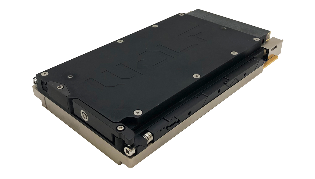
New VPX (VITA 46) and VPX-REDI (VITA 48) standards are heavily supported by the major military systems integrators and COTS suppliers such as Curtiss-Wright Controls Embedded Computing (CWCEC). A sample VPX-REDI module, CWCEC’s CHAMP-AV6 DSP is shown in Figure 1.
CWCEC will create the broad infrastructure needed for programs to adopt LRMs as their first-choice option, even for small volumes, with the proven confidence of future-proofed technology and cost structures offered by the COTS industry.
For more information, e-mail John at [email protected].

